Reverse engineering my cable modem and turning it into an SDR
Introduction
A few weeks ago I got curious about an old cable modem sitting in my closet, a Motorola MB7220. Initially I was interested in what kind of hardware it had and if it was running Linux. Some quick searching brought me to a thread on a web forum where people were discussing the built in spectrum analyzer feature used for diagnostics. Someone mentioned that they could see spikes corresponding to FM radio stations. This sparked a thought: if a cable modem and a digital TV tuner dongle are fundamentally doing the same thing (receiving and demodulating QAM signals), could a modem be turned into an SDR (software-defined radio) a la RTL-SDR?
Going into this project, I knew next to nothing about RF and had no idea if this goal was even feasible at all for the hardware. I found an SDR project based on an Analog Devices cable modem chip, as well as a forum thread where someone else was wondering about the same thing a few years ago.
The last post in the thread from user VK4HAT states:
I say if you have the skills, time and desire, give it a go and see where you end up. If google shows nothing, then its likely not been tried. With so few firsts available in life, take those that present themselves and have a crack, even if failure is always an option.
So that is exactly what I did.
Gaining Access
My first goal was to look for an access vector or a way to communicate with the device. I knew that there wasn’t much to see on the web interface and telnet was disabled, so I skipped ahead to opening it up.
After removing a few screws from the plastic housing to get access to the board, my first thought was to look for UART headers to take a peek at the serial console. After identifying two candidates consisting of four vias surrounded by a rectangle near the edge of the PCB, it was time to identify the pins. Using a multimeter, the ground pin can be easily identified by checking the continuity with one of the metal shields on board. The VCC pin can be identified by measuring the voltage of each pin when powering on the board. It should be a steady 3.3v, or in some cases 1.8v or 5v. This pin is not needed, but is still useful to identify the operating voltage and eliminate one candidate for the Tx and Rx pins. While booting, the Tx pin will sit on average a little lower than the VCC pin and drop much lower when a lot of data is being output. This leaves the last pin as Rx.
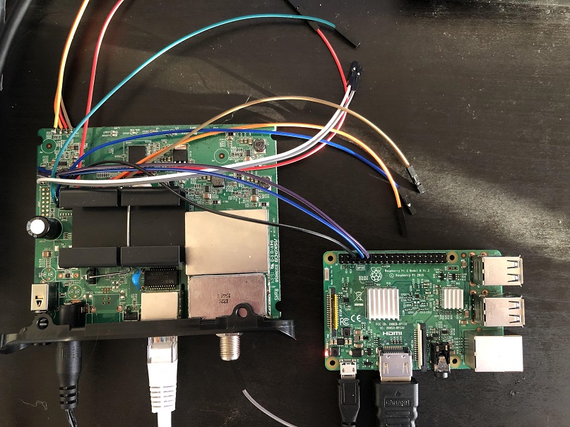
One of the UARTs identified earlier did not seem to be transmitting anything while the other did. After soldering some wires to the active UART, I connected the Tx to UART Rx GPIO pin on a Raspberry Pi, the Rx to the Pi’s Tx, and the ground to the ground pin. Note that this can only be done because both systems are 3.3v. Had that not been the case, a USB TTL adapter with an adjustable voltage level could be used just as easily, and is probably a better idea most of the time anyway.
There are a few reasons why the Raspberry Pi is not the best serial interface such as if you need parity or other features, but in this case I had it on hand and it works. The serial console of the Pi must also be disabled so that it can be freed up for other purposes. There is another reason I chose to use the Raspberry Pi which I will get to later.
Finally, to actually see the data I used the cu utility:
cu -l /dev/serial0 -s 115200
The baud rate was a lucky guess, but 115200 is very common on such devices.
If the baud rate is wrong you will quickly know when you see a bunch of garbage
on the screen. A logic analyzer could be used to definitively find the baud
rate and other parameters, but guessing is sometimes quicker and always
cheaper.
After powering on the device, the terminal filled with output:
pi@raspberrypi:~/modem $ cu -l /dev/serial0 -s 115200
Connected.
�
B3312inim S C 84(9 m
ose_VS 8
STesldlo rh 83 rs 10
STesldhi: _h 8, _s 13
Sync: 0
MemSize:            128 M
Chip ID:     BCM3383D-B0

BootLoader Version: 2.4.0 fyl spiboot reduced DDR drive avs
Build Date: Nov 12 2015
Build Time: 14:31:43
SPI flash ID 0xef4016, size 4MB, block size 64KB, write buffer 256, flags 0x0
Cust key size 128

Signature/PID: 3383


Image 1 Program Header:
   Signature: 3383
     Control: 0005
   Major Rev: 0003
   Minor Rev: 0000
  Build Time: 2015/11/26 08:47:57 Z
 File Length: 1692841 bytes
Load Address: 80004000
    Filename: ecram_sto.bin
         HCS: e749
         CRC: 175b753f

Found image 1 at offset 20000

Enter '1', '2', or 'p' within 2 seconds or take default...


Performing CRC on Image 1...
CRC time = 282177012
Detected LZMA compressed image... decompressing...
Target Address: 0x80004000
decompressSpace is 0x8000000
Elapsed time 736066500

Decompressed length: 8091524

Executing Image 1...


 eCos - hal_diag_init
Ecos memory map:
BLOCK    OWNER        MIPS      SIZE      MEM
Block 0: Owner: 0 - 0x00000000 0x07e00000 0x00000000
Block 0: Owner: 0 - 0 MB 126 MB 0 MB
Block 1: Owner: 3 - 0x07e00000 0x00200000 0x07e00000
Block 1: Owner: 3 - 126 MB 2 MB 126 MB
126MB (129024KB) remaining for eCos
Init device '/dev/BrcmTelnetIoDriver'
Init device '/dev/ttydiag'
Init tty channel: 807bb020
Init device '/dev/tty0'
Init tty channel: 807bb040
Init device '/dev/haldiag'
HAL/diag SERIAL init
Init device '/dev/ser0'
BCM 33XX SERIAL init - dev: b4e00500.2
Set output buffer - buf: 0x80852408 len: 4096
Set input buffer - buf: 0x80853408 len: 4096
BCM 33XX SERIAL config
Init device '/dev/ser1'
BCM 33XX SERIAL init - dev: b4e00520.3
Set output buffer - buf: 0x80854408 len: 4096
Set input buffer - buf: 0x80855408 len: 4096
BCM 33XX SERIAL config

Init device '/dev/ser2'
InitBoard: MIPS frequency 637200000

...

Reading Permanent settings from non-vol...
Checksum for permanent settings:  0xe9d88f65
Setting downstream calibration signature to '5.7.1mp1|die temperature:70.775degC'
Settings were read and verified.


Reading Dynamic settings from non-vol...
Checksum for dynamic settings:  0x6e4a329
Settings were read and verified.

Console input has been disabled in non-vol.
Console output has been disabled in non-vol!  Goodbye...
[00:00:00 01/01/1970] [Reset/Standby Switch Thread] BcmResetStandbySwitchThread::ProcessResetSwitchEvent:  (Reset/Standby Switch Thread) Reset switch released; resetting...
[00:00:00 01/01/1970] [Reset/Standby Switch Thread] BcmResetStandbySwitchThread::ProcessResetSwitchEvent:  (Reset/Standby Switch Thread) Cant Reset pfCmDocsisCtlThread==NULL...
This output contains a wealth of information. The device is running eCos on a MIPS processor which is part of a Broadcom BCM3383 SoC. It turns out there are actually two MIPS processors on this SoC although one of them is not used on this modem, explaining the other UART. On some devices, the second processor will run Linux for additional features.
Also, this seems like the end of the line for serial because shortly after booting the actual OS, it disables the serial console. Hitting “p” at the bootloader prompt does not lead to much except a way to download new OS images via tftp and a utility to read and write memory addresses. This could be used to bypass the check, but a much greater understanding of the OS and memory layout would be required.
Dumping the flash
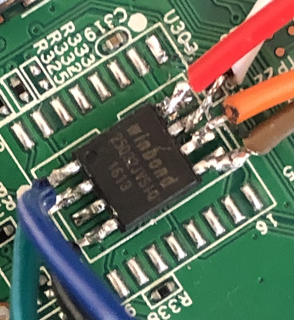
My goal now was to enable the serial console. Examination of the board reveals a single SPI flash chip which likely contains the bootloader, OS, and configuration as it is the only non-volatile storage visible on the board.
This is where the Raspberry Pi comes in handy once again. The GPIO header also conveniently contains a SPI interface which can be used to read the data off of the flash chip.
Searching the number on the chip, “winbond 25Q32JV”, yields the datasheet containing the pinout. The important ones are VCC, Chip Select (CS), Clock (CLK), Data Out (DO), Data In (DI), and ground.
One common issue with dumping a SPI chip on a board is that the chip requires power, but this will also usually power the board and cause it to start booting and using the chip. I chose to overcome this by heating the VCC pin with my soldering iron and very carefully lifting it off the pad. This is a convenient, but rather crude solution which may result in snapped off leads so use at your own risk! I also soldered a jumper wire to the pad and another to the floating leg so that I could easily connect and disconnect them and allow the device to boot again.
Another note, on some boards the Chip Select pin is assumed to always be enabled so it is directly tied to VCC. This means when you power the CS pin, the board also starts booting. This can be solved in a similar way to the VCC pin.
Now, wires can be soldered to the rest of the pins and the they can be
connected to the Raspberry Pi. The ground goes to ground (the UART ground
from earlier can also be used), the VCC to the Pi’s 3.3v pin. (Again, it is
critical to verify with the datasheet that this is a 3.3v chip because the Pi
only supports 3.3v). The DO pin is connected to the Pi’s SPI MISO (master in
slave out) pin and DI to the MOSI pin (master out slave in). Lastly, the
Clock is connected to the SCLK GPIO pin and the Chip Select to the CE0 pin.
 |
|---|
| Not the best soldering job but it will work |
To actually read the chip, there is a fantastic tool called
flashrom which supports an enormous number of
chips. flashrom is present in the repos of many distributions including that
of the Raspberry Pi OS (formerly known as Raspbian).
Luckily the W25Q32JV is supported, under the name “W25Q32.V”. A quick check on the flashrom wiki shows the size and voltage match what is expected and that the chip is fully supported.
Before proceeding, ensure that the SPI interface on the Pi is enabled by
using the raspi-config utility and checking under “Interfacing Options”.
At last we can read the chip. First verify that it is detected and everything is wired correctly:
flashrom -p linux_spi:dev=/dev/spidev0.0,spispeed=2000 \
    --chip W25Q32.V
If that succeeds we can now dump the contents:
flashrom -p linux_spi:dev=/dev/spidev0.0,spispeed=2000 \
    --chip W25Q32.V \
    --read modem.bin
Firmware Analysis
A quick glance at the hexdump reveals that most of the data is compressed or encrypted but near the end, the configuration is visible.
...
003f00c0: ffff ffff ffff ffff ffff 0000 07b0 369a  ..............6.
003f00d0: 6336 0010 434d 4170 0002 0000 0002 0000  c6..CMAp........
003f00e0: 0000 0057 4d4c 6f67 0005 0004 7573 6572  ...WMLog....user
003f00f0: 0004 7573 6572 0005 6164 6d69 6e00 086d  ..user..admin..m
003f0100: 6f74 6f72 6f6c 6102 7465 6368 6e69 6369  otorola.technici
...
The web interface credentials are plainly visible as well as many other encoded configuration values.
After some searching, I came across a great project called bcm2-utils which contains utilities to dump, parse, and modify the configuration on Broadcom cable modems. The repo also contains a lot of very detailed documentation on the format of the firmware and configuration. As a quick note, the dumping feature requires either telnet or serial connection, neither of which were available on my device.
The start of the configuration is actually at 0x003f0000 on my device and
includes the 202 0xff bytes. After extracting just the config from the dump,
I was able to successfully read it with bcm2cfg.
I enabled the serial console as well as telnet access and set a simpler telnet password.
$ ./bcm2-utils/bcm2cfg set bfc.serial_console_mode "rw"
bfc.serial_console_mode = rw
$ ./bcm2-utils/bcm2cfg set userif.remote_acc_methods 0x3
userif.remote_acc_methods = http | telnet
$ ./bcm2-utils/bcm2cfg set userif.remote_acc_pass abcd
userif.remote_acc_pass = abcd
Next, I appended the modified configuration onto a file padded with zeros up
to the appropriate offset and used flashrom to write the configuration back
to the chip.
To avoid rewriting the entire chip, I created a layout file for flashrom so it
would only overwrite the configuration rather than the entire contents which is
why the modified image is just padded with zeros.
The layout file looks like this:
00000000:003effff fw
003f0000:003fffff cfg
and the command:
flashrom -p linux_spi:dev=/dev/spidev0.0,spispeed=2000 \
    --chip W25Q32.V \
    --layout ./layout \
    --image cfg \
    --write modem-modified.bin
After opening the serial console and booting again, I am greeted with… the exact same thing as before.
Closer examination of the flash image shows that there are a number of repeated copies of the configuration following the initial one. These have slight differences, the most obvious being additional error log messages. It appears that the device keeps rolling backups of the configuration in case one gets corrupted.
To simplify things, I did a factory reset through the web interface to get rid
of all the error log messages. Then I dumped the flash again and repeated the
previous process to modify the clean configuration except this time I truncated
the config to only include the first copy. Then using some dd commands I
would rather not think about, I reconstructed the entire configuration section,
appending the modified config at each offset where a copy of the config
started.
After flashing this new image and booting once again, I am finally able to view the entire boot log and then have access to a console, although the output is being flooded by a process looking for a signal.
...

Reading Permanent settings from non-vol...
Checksum for permanent settings:  0xe9d88f65
Setting downstream calibration signature to '5.7.1mp1|die temperature:70.775degC^@^@^@^@^@'
Settings were read and verified.


Reading Dynamic settings from non-vol...
Checksum for dynamic settings:  0x2630e508
Settings were read and verified.

[00:00:00 01/01/1970] [tStartup] BcmBfcFpmDriver::Init:  (BFC FPM Driver) Setting FPM Buffer size to: 256 Base Address: 0x87566600
[00:00:00 01/01/1970] [tStartup] BcmBfcFpmDriver::Init:  (BFC FPM Driver) fFpmLargestBufferSize: 2048 fFpmSizeShiftBits: 0x8
[00:00:00 01/01/1970] [tStartup] BcmBfcFpmDriver::Init:  (BFC FPM Driver) Pool index: 0  pool size: 2048
[00:00:00 01/01/1970] [tStartup] BcmBfcFpmDriver::Init:  (BFC FPM Driver) Pool index: 1  pool size: 1024
[00:00:00 01/01/1970] [tStartup] BcmBfcFpmDriver::Init:  (BFC FPM Driver) Pool index: 2  pool size: 512
[00:00:00 01/01/1970] [tStartup] BcmBfcFpmDriver::Init:  (BFC FPM Driver) Pool index: 3  pool size: 256
[00:00:00 01/01/1970] [tStartup] BcmBfcFpmDriver::Init:  (BFC FPM Driver) Lookup table index: 0  pool size: 3

...

[00:00:18 01/01/1970] [Scan Downstream Thread] BcmGenericCmDownstreamScanThread::ThreadMain:  (Scan Downstream Thread) Scanning for a Downstream Channel...
[00:00:18 01/01/1970] [Scan Downstream Thread] BcmGenericCmDownstreamScanThread::ScanStarting:  (Scan Downstream Thread) Scanning STD & HRC Annex B channel plan frequencies
Resetting EnergyDetected to false.
Forgetting energy frequency.
Executing fast scan algorithm...

Type 'help' or '?' for a list of commands...

CM> Scanned 489000000 Hz...
Scanned 495000000 Hz...
Scanned 501000000 Hz...
Scanned 507000000 Hz...
Scanned 513000000 Hz...
eCos Console
The eCos console contains many configuration and debugging commands. The process flodding the output can be stopped with the following commands:
cd cm_hal
scan_stop
As a side note, these “directories” are not a real filesystem, they are just a way of organizing groups of commands.
Telnet access also works at the IP address 192.168.100.1. The username is
“technician” and the password is what I changed it to earlier when modifying
the configuration. Telnet puts you into a limited version of the shell, but
the full shell can be accessed with the su command and the password brcm
when prompted (credit to jclehner, author of bcm2-utils for that one). This
password may vary depending on the device manufacturer.
Initially, I just wanted to see if I could enable the web-based spectrum analyzer which seems to be disabled on this device. There were some settings related to it, but nothing about enabling or disabling the external interface.
After spending several hours poking around in the various menus and commands I decided it was time to move on to analyzing OS.
Reverse engineering the firmware
Thanks to the boot log, we know the OS is located at 0x20000 and is LZMA compressed.
The README of bcm2-utils pointed me to a
Broadcom repo
containing a utility called ProgramStore for extracting the OS image.
After building ProgramStore I was able to extract the decompressed image with
the following command:
./ProgramStore -f ./ecram_sto.bin -o decompressed_fw.bin -c 4 -x
Now we can throw it into Ghidra using the base address from the boot log, 0x80004000 and setting the architecture to big endian MIPS.
After running the auto analysis it’s time to start digging around. Fortunately, there a lot of debug strings that makes some functions very easy to identify.
I started naming any functions I came across using the strings as well as the function signature in combination with the context it is used and any cross references. Eventually, when ending up in an unknown function, the cross references to named functions give some clue as to the context of the function eventually making things a little easier.
For the most part, I was just searching interesting strings such as “tuner” and “ADC” and trying to understand as much as I could, going wherever the various function calls took me and keeping notes on interesting functions, structures, addresses, and theories for how things worked in a separate text document.
One useful feature of the eCos console is the call command which allows you
to call a function at an arbitrary address with the the given arguments. This
allows us to actually execute a function to test a hypothesis about what it
does.
The operating system has a large amount of Broadcom code on top of it which is all written in C++. This makes reversing it significantly more annoying by adding a lot of indirection when it comes to function calls and polymorphism. For example you will often see code like this:
case 0x24:
    uVar23 = (**(code **)(*piParm1_00 + 0x1c))(piParm1_00);
Not only does this make the code very hard to follow, it also means Ghidra cannot track cross references to functions that are called in this way.
Sometimes the class can be determined by following the object pointer all the
way back to where it is initialized, but other times it is easier to just patch
a function where the unknown object is used to write the vale of the pointer
to a known location and then return. This can be done with the write_memory
command in the eCos console. Then the call command can be used to call the
function containing the unknown object and then read_memory can be used to
retrieve the pointer from the known location. These type of hacks as well as
combining static and dynamic analysis are crucial to avoid getting stuck.
Some functions would cause the device to crash when I tried to call them. Closer inspection shows they are taking more than 4 arguments and using the t0, t1, t2, and t3 registers for the additional arguments. This is a little unusual for a 32-bit MIPS device, but as it turns out the calling convention is determined by the ABI and MIPS has a number of different ABIs. It is suprisingly hard to find information about the exact calling conventions, but using Godbolt, I was able to determine that EABI is the most likely candidate which uses t0-t3 for additional arguments. Unfortunately, Ghidra does not seem to support MIPS EABI, but manually setting the argument registers on a few functions is not too inconvenient and the arguments seem to be the only consequential difference.
After digging around for a while, I set my sights on the spectrum analyzer. I was never able to figure out how to enable the web interface, although the code for it was there.
I found many other useful functions such as those used to set the frequency of a downstream (recieving) channel, the socket/bind/listen/send/recv functions, thread creation functions, and functions for reading and writing to registers of tuner and LNA (low noise amplifier).
Breakthrough
Eventually I found a console command to perform a bandpower measurement for a given frequency range.
I began closely following the execution to see what it does with the frequency range arguments and found that it calls a very familiar function - almost identical to the one used to tune downstream channels, but the memory mapped register addresses where the frequency is set are just above those used for normal channels. This suggests that the spectrum analyzer uses an extra channel that otherwise operates in a very similar way to the normal downstream channels with regards to tuning and setting the gain.
Continuing on, the measurement function writes the physical address of a destination buffer to a memory mapped register and then sets a bit in another register and loops until it is unset again. Then it calls the function that presumably computes an FFT, passing in buffer address. After the computation, another function does some processing on the buffer, but leaves it otherwise intact.
After sticking a jumper wire into the coaxial connector to act as as an
antenna, I called the bandpower function and then did a read_memory on the
destination buffer.
CM> read_memory -n256 0x86fb3e80

86fb3e80: 00 00 06 8c  00 3f fe 48  00 00 06 41  00 20 00 3d | .....?.H...A. .=
86fb3e90: 00 00 08 56  00 20 02 11  00 00 0a b3  00 20 03 f2 | ...V. ....... ..
86fb3ea0: 00 00 0a 50  00 20 04 84  00 00 06 61  00 20 03 d7 | ...P. .....a. ..
86fb3eb0: 00 00 01 1d  00 20 02 da  00 1f fd f4  00 20 00 4d | ..... ....... .M
86fb3ec0: 00 1f fd 11  00 3f fc 20  00 1f fb 95  00 3f fa ad | .....?. .....?..
86fb3ed0: 00 1f fa 32  00 3f fd fc  00 1f fc a3  00 20 00 cb | ...2.?....... ..
86fb3ee0: 00 00 01 97  00 3f fe b5  00 00 04 0f  00 3f fb 6a | .....?.......?.j
86fb3ef0: 00 00 03 9f  00 3f fb d6  00 00 03 1d  00 3f fe 55 | .....?.......?.U
86fb3f00: 00 00 02 f8  00 3f ff a9  00 00 02 ee  00 20 01 49 | .....?....... .I
86fb3f10: 00 00 03 8f  00 20 04 87  00 00 03 94  00 20 05 09 | ..... ....... ..
86fb3f20: 00 00 01 81  00 3f ff bb  00 1f ff 14  00 3f fa 97 | .....?.......?..
86fb3f30: 00 1f fe 8d  00 3f fc 9d  00 1f ff 89  00 20 01 82 | .....?....... ..
86fb3f40: 00 00 00 be  00 20 00 09  00 00 01 8f  00 3f fa 3a | ..... .......?.:
86fb3f50: 00 00 01 78  00 3f fa 66  00 00 00 7b  00 20 01 35 | ...x.?.f...{. .5
86fb3f60: 00 1f ff 79  00 20 04 f6  00 1f fe e2  00 20 02 62 | ...y. ....... .b
86fb3f70: 00 1f fd 93  00 3f ff 4d  00 1f fa ee  00 3f fe 16 | .....?.M.....?..
My hope was that this was I/Q data and this certainly looked promising. This was supported by the function that processes the data after the FFT - it checks if the 0x00200000 bit is zero on the first 32-bit word, and if so drops the first and last word of data. I hypothesized that this bit indicates if the sample is an I or a Q value, and if the first sample is a Q, it drops the unmatched Q from the beginning and unmatched I from the end. For example:
Case 1:                Case 2:
Q IQ IQ IQ I           IQ IQ IQ IQ

     |                      | do nothing
     v                      v

  IQ IQ IQ             IQ IQ IQ IQ
The only way to know for sure was to grab some more data and analyze it.
Hello World
To make things easier going forward, I decided to write a program that would run on the modem to call the tune and bandpower functions, and then open a listening sock and send the contents of the buffer back over a TCP connection. I should also note I stopped working on the Raspberry Pi at this point so that I would not have to create an ARM-to-MIPS crosscompiler.
The basic approach to write code that can be loaded and executed on “almost-bare metal” is as follows.
By adding the signatures of the external functions we wish to use to a header file and using a linker script containing the addresses of the functions, it is easy to compile a program that utilizes these functions. Additionally, to make the program work when loaded at a predetermined memory location and ensure the entry point is at that address, a section map is be used. The linker script looks something like this:
memset = 0x80522d7c;
memcpy = 0x80004f30;
malloc = 0x80596998;
printf = 0x8052b178;
socket = 0x80332fd0;
bind = 0x800ae7bc;
listen = 0x80412ed4;
accept = 0x80413118;
send = 0x80413240;
recv = 0x804134bc;
tune_aux_channel = 0x80082108;

SECTIONS
{
  . = 0x80810000;
  .start : { *(.start) }
  .text : { *(.text) }
  .data : { *(.data) }
  .rodata : { *(.rodata) }
}
It is built with the following command:
mips-linux-gcc measure.c \
    -march=mips32 \
    -mabi=eabi \
    -msoft-float \
    -mno-abicalls \
    -fno-builtin
    -nostdlib \
    -nodefaultlibs \
    -nostartfiles \
    -T ./script.ld
The MIPS CPU does not have an FPU so -msoft-float is used. -mno-abicalls
seems to be required when using -mabi=eabi. -fno-builtin prevents the
compiler from optimizing certain sections by adding calls to functions like
memcpy which would result in an undefined symbol. -nostdlib and
-nostartfiles prevent the compiler from using the standard c library the
“crt0.o” entrypoint which does some setup we do not care about.
Using objcopy we can extract just the sections we care about out of the
compiled elf.
mips-linux-objcopy -O binary \
    -j .start \
    -j .text \
    -j .data \
    -j .rodata \
    a.out bin
And finally, to actually load it I wrote a Python script that uses pexpect to
telnet into the modem and write the binary to the target address using the
write_memory command. The program is executed with the call command.
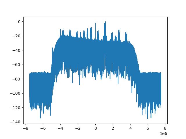
To see if I could pick up FM radio broadcasts, I tuned it to 100MHz and grabbed some data.
Using the numpy, scipy, and matplotlib Python libraries, I was able to interpret the data a complex valued samples, compute an FFT and plot it to see a nice band pass filtered spectrum with distinct spikes.
 |
|---|
| The plotted frequency spectrum |
At the time I was still not really convinced, but in retrospect this really does demonstrate that I had successfully captured complex samples as such a plot would not be possible with the my script were that not the case.
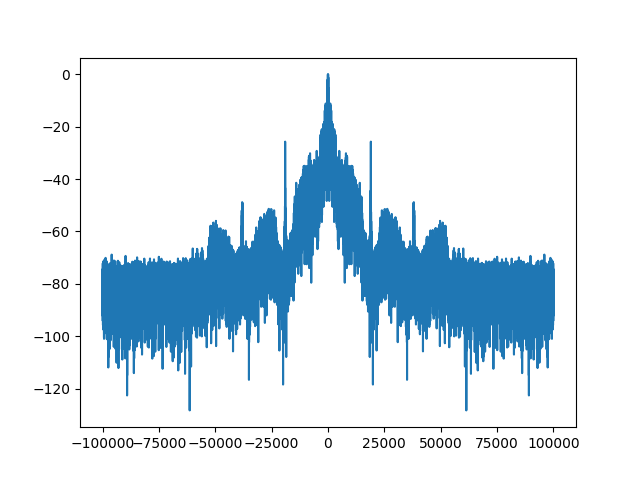
I was not going to be fully convinced until I could demodulate the signal and listen to the FM radio broadcasts. Shifting the spectrum to center one of the spikes, decimating it to isolate the frequency range, and using a very simple demodulation technique I found online for complex-valued FM, I was able to clearly see the different parts of the broadcast including the (what should be) 19kHz pilot tone.
 |
|---|
| The frequency spectrum of the demodulated signal |
With some experimentation, I determined that a sample rate of 15 million samples per second puts the pilot tone right at 19kHz. This seems consistent with the fact that the bandpower function measures in blocks of 7.5MHz. Although you get a full 15MHz since these are complex-valued samples, the usable range of the band pass filter is more like 7.5-8MHz with an assumed 15MHz sample rate which matches up.
Optimizations
At 15 million samples per second and each sample with occupying 8 bytes, less than a second of data can be stored in the approximately 100MB of free RAM.
One obvious improvement would be to send the data after filling the buffer and then capture more data. The processing time and network throughput meant that there was about an 11 second gap between captures. This was cut down to about 5 seconds by implementing a new function that sets up the registers and initiates the capture, eliminating the FFT calculation and other processing.
After some experimentation with the unknown register values in hopes of finding
one that would affect the sample rate, I found a bit that appears to limit the
I and Q values to 14 significant bits. While they were still occupying 8 bytes
per sample, this meant I could pack two of them into a single 32-bit word.
Note: I am not sure the ADC is actually sampling 14 / 20 bits as that seems
rather high, but that is the effective size of each sample value.
I wrote another function to process each capture, determine if it starts with an I or a Q value and then iterate through the buffer packing each I/Q pair into a single integer and writing it to the next position in the buffer. This alone did not improve the performance much, but by only taking every Nth sample, I could lower the effective sample rate, shorten the processing time, and reduce the number of bytes I had to send back which greatly improved the latency.
Another improvement was threading. I found the functions used to create and start new threads as well as those used for counting semaphores on the OS thanks to some debug messages. With these tools, I could have two or more buffers. Then one thread continuously captures data into the next available buffer and then signals another thread with a semaphore that it is done writing. The second thread packs and downsamples the data, sends it over the network, and then signals that the buffer is available to be written to again.
With these improvements and the sample rate reduced by a factor of 32 (down to 464kHz), I could endlessly capture and send data while dropping about 12%. I believe this is mostly due to a few milliseconds of inherent latency between when the capture is finished and the “done” flag is set. Additionally, I do not know if there is a way to generate an interrupt or something when it finishes so I have to restort to sleeping in a while loop since that is how it is done in the original function.
My hope is that there is some sort of clock divider register to reduce the clock of the ADC to lower the sample rate which may reduce this latancy and eliminate postprocessing time, but I have not yet found one.
Downsampling this way seems to lose a lot of the information - past about 16 times the noise floor is a lot higher and the stereo channels of FM radio broadcasts are no longer discernable.
Although dropping some data is bad some some applications, it can stream FM radio fairly seamlessly, although the audio has to be slowed down slightly so it is not consumed faster than it is being recieved. I have also been able to be recieved. I have also been able to pick up the 154MHz narrowband FM radio used by the local fire department.
Here is a short sample of some demodulated audio captured with the modem
Conclusion
Although this project was mostly just a challenge to myself and is not intended as a serious SDR, I am satisfied with the results and hope to continue to improve it.
This quote really resonated with me, so once again in the words of VK4HAT, “With so few firsts available in life, take those that present themselves and have a crack”